

My previous post, How to Convert Your Ebike to a Solar Ebike, was an introduction to this topic. Please read that first, if you haven’t already. This post will cover a range of recurring questions I’ve been answering over the years via email and in comments on YouTube, InstaGram, and ebike forums about the nitty gritty details of matching an ebike battery, solar charge controller and a solar panel to each other to create an efficient system which performs well over the full range of real-world conditions.
My goal is to help you design a system which will extract the maximum amount of energy from your solar panel whether it is cold or hot. Don’t worry if you don’t fully understand everything here on your first reading. Most first-time solar bike builders got things working without a full understanding of every last detail. I certainly did. You can always come back and use this as a troubleshooting guide if things aren’t working.
Some electrical engineers will feel compelled to point out that as a non-electrical engineer I have no business giving advice about engineering electrical systems. They are right. I’m just a fool with a blog who has been tinkering around with this stuff long enough that I’ve made most of the mistakes it’s possible to make. I’m here to share what I’ve learned so you can get your project up and running before you make your first expensive mistake and get hurt or get frustrated and give up.
Battery
I’m assuming you already have an ebike so you already have the three components on the right: battery, motor controller and motor.
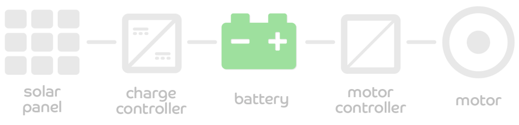
For our solar upgrade project, we’ll be working with the three components on the left. You might be tempted to start with the solar panel but we’re going to start with the battery and work our way back to the solar panel because the battery’s chemistry, number of cells and cell ratings determine our system’s voltage range and maximum current when charging. These values will drive our choices for the other components.
The most common ebike batteries are 36V, 48V or 52V. These values are “nominal” voltages meaning they roughly correspond to the average voltage of the battery pack as it is discharged from full to empty. If your bike uses another voltage like 24V or 72V you’ll need to do your own calculations but the same basic principles still apply. For our purposes, we will need to know the actual maximum and minimum values. A “36 volt” battery typically consists of 10 lithium ion cells connected in series. A single cell is at 4.2 volts when full and the voltage gradually decreases as it is discharged.
The pack’s BMS (Battery Management System) will disconnect the battery to protect the cells from over-discharge when the voltage falls below the LVD (Low Voltage Disconnect) value which is typically 3.0V/cell but may be as low as 2.7V or as high as 3.3V. This cut-off point usually happens under load and as soon as the load is disconnected, the cell voltage may rebound a bit but if the battery is discharged slowly it may stay at the LVD value. Here’s a summary of the numbers we will need.
| 36V | 48V | 52V | Nominal battery voltage |
|---|---|---|---|
| 10 | 13 | 14 | Cells in series |
| 27.0 | 35.1 | 37.8 | Lowest minimum voltage (2.7V/cell) |
| 30.0 | 39.0 | 42.0 | Recommended minimum voltage (3.0V/cell) |
| 33.0 | 42.9 | 46.2 | Highest minimum voltage (3.3V/cell) |
| 42.0 | 54.6 | 58.8 | Maximum voltage (fully charged, 4.2V/cell) |
I used words like “typically” and “usually” above because there are many different flavors of lithium battery chemistry and some of them have different minimum and maximum voltage values. Make sure you understand your battery’s limits before connecting a solar charge controller. Over-charging or accidentally short-circuiting lithium batteries can cause them to emit toxic smoke or start a fire. The labels printed on your battery pack or the charger which came with your bike are good starting points.
You’ll also need to consider how much charge current your battery pack can handle. A small, inexpensive pack’s BMS may impose a maximum charge current as low as 2 amps. With a 36V battery, that means that if you connect a 100 watt solar panel to an empty battery (~30V), the charge controller will deliver more than 2A of charge current and the BMS may stop charging. Since neither one of our solar charge controllers has the option to limit charge current, you would need to select a smaller solar panel or get a different battery if you run into this limitation. Your battery cells are likely rated for higher charge current than the BMS allows so it may be necessary to bypass the current limit by charging the pack through the larger discharge wires but doing so may also bypass important safety feature like cell balancing and disconnecting the charge current if any one cell exceeds 4.2 volts or if the pack gets too hot. Bypassing the charge port falls under “advanced users only” so proceed with caution if you understand the risks.
Solar Charge Controller
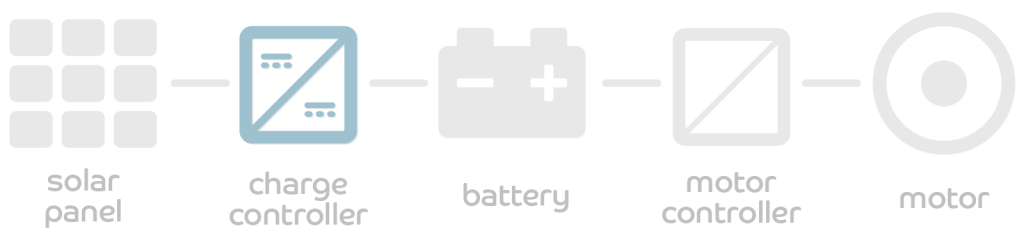
Now that we have our battery’s critical numbers, we can move on to our boost solar charge controller. This device converts lower DC voltage from the solar panel (input) to higher DC voltage needed to charge our battery (output). If you’re getting the Genasun GVB-8-WP, you’ll need to order the model which has been factory programmed for your battery’s maximum voltage. Get the one that is as close to your battery’s maximum voltage as possible without going over. The currently offered models are 41.7V for a 36V battery, 54.2 for a 48V battery, and 58.4V for a 52V battery. If you’re getting the CTK-EV300 charge controller then you’ll need to program it yourself for the voltage you need. Remember to use the “SELF” voltage option as the built-in 24V/36V/48V presets are intended for lead batteries.
Solar Panel
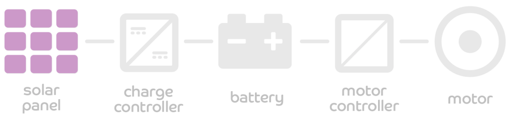
My background is in roof-mounted residential and commercial solar electric systems. In that world, we seek to optimize the design for maximum annual energy production from each solar panel. However, most systems end up being a compromise of production yield, cost and aesthetics.
On a bicycle, it is especially important to extract every last bit of potential energy from the solar panel at all times as this allows us to carry the smallest and lightest panel that meets our energy needs. On a long tour, we will occasionally end up having to pedal up a steep hill with no electric assist because the sun isn’t available and every extra bit of weight is going to be a curse. Selecting the best solar panel for our ebike project is a topic for a future post. For now, let’s focus on the electrical specifications and how they relate to the overall system.
This part gets a little tricky because a solar panel’s voltage and current is determined by the temperature of the solar cells, irradiance (amount of sunlight) and the electrical load on the panel. To ensure the charge controller will be able to charge our battery under all conditions, we need to account for temperature. The VMP and VOC values on the label are only valid at STC or “Standard Test Conditions”, defined as 25°C solar cell temperature and 1000 W/m2 irradiance. Most of the time, your solar panel’s cells will be significantly warmer than 25°C and less than 1000 W/m2 which is why your panel’s peak output is typically only about 85-90% of the rated Pmax value and the charge controller’s output is around 70-85% of the Pmax due to 5-15% DC-DC conversion losses. There are four things you need to consider.
The panel’s highest voltage should never exceed the battery’s lowest voltage
We’re using a boost charge controller which means that it takes the input voltage from the solar panel and outputs a higher voltage to the battery. If your solar voltage is ever higher than the battery voltage, your charge controller will detect it as an error condition and will refuse to charge the battery. Even though you typically don’t discharge your battery to the lowest voltage it can safely handle, if it ever happens while you’re touring you don’t want to get stuck in a situation where your solar panel voltage is too high to charge your battery. The solar panel’s highest voltage will occur on a cold morning when the temperature is around 0°C (32°F). In this scenario, charging has not started yet so there’s no load on the panel which means we need to consider the open circuit voltage (VOC). The solar panel voltage will be even higher at lower temperatures but lithium batteries should never be charged below 0°C.
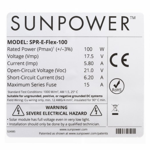
For example, the VOC of this Sunpower SPR-E-Flex-100 panel is 21.0V at STC (25°C) but what will it be at 0°C? From the datasheet (PDF), the temperature coefficient for voltage is -0.28%/°C. Since 0°C is 25° below the STC temperature, we take (0-25) * -0.28% = 7% which gives us a 1.07 multiplier to covert from voltage at STC to voltage at 0°C for any similar Sunpower panel. In this case, 21.0V * 1.07 = 22.5V which is what our charge controller will detect on the input side. Since 22.5V is lower than the lowest battery voltage for our 36V, 48V and 52V batteries, this panel is suitable for charging a depleted battery under these conditions. If you want to connect two of these panels in series, you would have 22.5V * 2 = 45.0V on this cold morning which would be too high to charge the 36V and 48V batteries but might be ok for the 52V as long as it has a little bit of charge left (45/14 = 3.2V/cell).
| 36V | 48V | 52V | Nominal battery voltage |
|---|---|---|---|
| 28.0 | 36.4 | 39.3 | Maximum recommended solar panel VOC at STC (label value) |
| 30.0 | 39.0 | 42.0 | Maximum recommended solar panel VOC at 0°C |
The panel’s lowest voltage should never drop below the charge controller’s lowest MPPT tracking voltage
On the hot end of the temperature scale, our solar panel’s lowest voltage will occur on a very hot day when there’s no air flow and the panel is under load. To calculate this voltage, we’ll use the maximum power point voltage (VMP) and a cell temperature of 75°C. Using our Sunpower panel, this gives us a correction factor of 1 + (75-25) * -0.28% = 0.86. Using our VMP, we get 17.5V * 0.86 = 15.05V. This value is well above the 5V minimum input voltage for the GVB-8 and just barely above the 15V minimum MPPT voltage for the CTK-EV300 so these panel and charge controller combinations should perform well across the entire temperature range. You will find that you’ll get similar values with most “nominal 12V” solar panels but be careful with smaller panels which may have lower voltages which may drop below the minimum required input voltage on a hot day.
The panel’s maximum current (IMP) should not exceed the charge controller’s maximum input current
This is unlikely to be a problem with one solar panel but if you connect two or more solar panels in parallel to the same solar charge controller to increase current, you’ll want to make sure the total current is lower than the charge controller’s maximum input current. Exceeding this limit will cause a properly designed charge controller to “clip” or “self derate” by lowering the input voltage and reducing the output power of the solar panels to less than the maximum possible under the current temperature and irradiance conditions. You’ll be losing potential solar watt-hours and you’ll be reducing the lifespan of your charge controller by running it too hot. A poorly designed charge controller may overheat and shut off or fail. Fortunately, this is easily fixed by adding a second charge controller and connecting the outputs in parallel.
The Genasun controller’s manual says you can go up to 9A of input current. The manual that came with my CTK-EV300 doesn’t indicate a maximum input current but claims “≤ 300W” power. If we assume this was measured at the maximum input voltage of 50V, that would indicate 6A max input current. This is consistent with anecdotal reports I’ve read that this unit tends to overheat if connected to more than 200 watts of solar panels. Your input voltage is likely to be lower than 50V so it makes sense that realistic working limit is closer to 100-150 watts, depending on your input and output voltage.
The panel’s maximum power must not exceed the battery’s maximum charging current
Plug-in chargers come with simple, straight-forward charge current ratings like “2 amps” or “4 amps.” This is made possible by the fact that the AC wall outlet (mains/grid) is a constant and effectively unlimited power source. Your solar charge controller is designed to always output the maximum power possible under the current solar conditions. These vary significantly over time and depend on the size of your solar panel so it’s not as simple to know the maximum output current. It’s up to you to ensure that the maximum output current does not exceed your battery pack’s ability to handle the current.
The highest sustained charge current will occur when the battery is at it’s lowest voltage and solar conditions are absolutely ideal. Even if your 100 watt solar panel typically outputs 80 watts, on a cold, sunny day you may see it sustain 100 watts long enough to be a concern if your battery can’t handle the extra input current. You need to plan for this scenario by sizing your solar panel to match your battery.
For example, RadPower ebikes all ship with a 2A charger so we know the battery can handle at least 2A of charge. However, their 48V 14Ah battery uses Samsung 35E cells. According to the 35E cell datasheet, these cells are rated for up to 2A of charge current per cell. With 4 cells in parallel, that gives a theoretical maximum charge current of 8A for the pack. However, the charge port is a relatively tiny 5.5mm barrel plug which certainly cannot handle 8A and the BMS most likely wouldn’t accept an 8A charge on the charge port. In this case, you could try going to 3A or 4A on the charge port and seeing if the plug gets too hot and if the BMS will cut off or will allow it. If that doesn’t work, you could try charging the battery through the discharge wires (see warnings above). Samsung recommends 1A per cell charge current for maximum cycle life so I would suggest keeping the “typical” solar charge current to 4A for this pack. Occasional spikes to 6A or 8A during regenerative braking and super-optimal solar conditions will probably be fine.
Conclusions
If you’re reading this far, you’re probably pretty serious about building a solar ebike. Hopefully, this has been helpful in selecting the right components for your project. Maybe you figured out that you need two solar charge controllers instead of just one or that you need a second battery to handle all the power from your large solar array. If you’re starting small with just 50-200 watts of solar panels then you’ll probably be fine with a single solar charge controller and your current 36V, 48V or 52V battery. You’ll find that most solar panels fit within the current and voltage limits outlined here. Things can get trickier as you add more solar panels so remember to review all the specs when you upgrade.

I used my solar bike to charge the wife’s RadPower bike on a long ride. My Genasun put out too much current and blew the (smartly) easily accessible 5 amp fuse on the charging input on the Rad battery. Now I know to tilt a panel away from the sun a little and watch the CA-3 when doing this in the future.
LikeLike
That’s lucky. Fuses have saved my bacon a bunch of times. You might be able to charge through the discharge connectors but they can be tricky to access and you really want to know exactly which cells your pack is using so you can go look up the specs so I’m always hesitant to advise that route.
LikeLike